GEOTECHNICAL ENGINEERING
CASPER WYOMING
HomeGeophysicsSeismic tomography (refraction/reflection)

Seismic Tomography (Refraction/Reflection) for Subsurface Imaging in Casper Wyoming

Evidence-based design. Reliable delivery.

LEARN MORE

The shallow bedrock and variable overburden across Casper Wyoming demand a subsurface investigation method capable of resolving sharp velocity contrasts without the ambiguity that often plagues conventional geotechnical drilling. Winter freeze-thaw cycles along the North Platte River corridor create fractured sandstone lenses that standard SPT drilling can easily miss, while the transition from floodplain alluvium to the Casper Formation sandstone occurs over just a few hundred feet laterally. Seismic tomography, combining refraction and reflection acquisition geometries, maps these transitions by inverting first-arrival traveltimes and stacked reflection events into a continuous P-wave or S-wave velocity model. The technique works particularly well where the water table sits within 15 to 30 feet of grade, a condition common in Natrona County, because saturated sediments produce a diagnostic velocity increase that delineates the groundwater surface without requiring a single borehole. When bedrock rippability or fault avoidance governs foundation design, the velocity cross-section from seismic tomography becomes the primary deliverable that structural and geotechnical engineers rely on, often supplemented by targeted SPT drilling at anomaly locations identified in the processed profile.

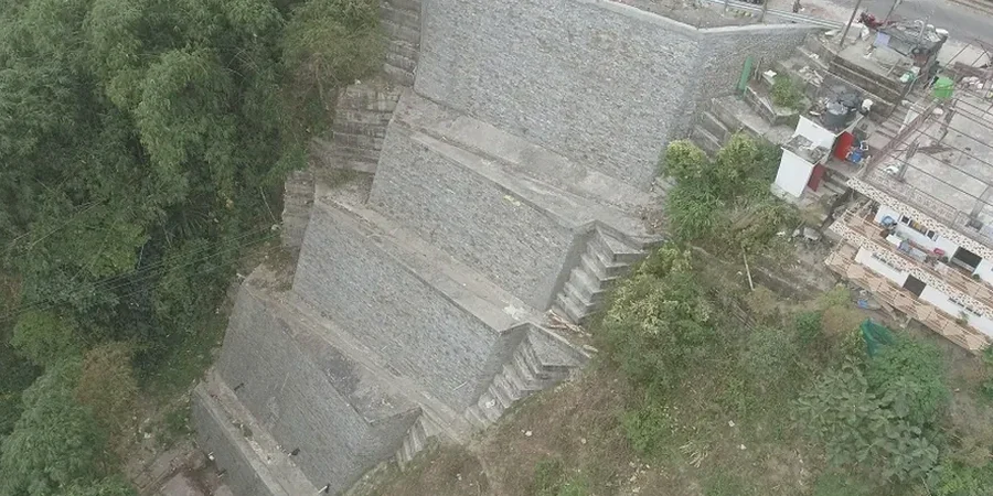
A seismic velocity cross-section resolves the transition from weathered to competent sandstone with greater lateral continuity than any feasible grid of boreholes.

Our service areas

How we work

The Casper Formation, a Pennsylvanian-age interbedded sandstone and siltstone unit exposed along Casper Mountain, exhibits seismic velocities ranging from 2,400 to 3,800 m/s in competent sections but drops below 1,600 m/s where jointing and paleo-weathering have softened the rock mass. Seismic refraction tomography resolves these weathered horizons as a gradual velocity gradient rather than a discrete layer boundary, which is geologically realistic for the saprolitic profiles found on the Laramie Range foothills. Acquisition geometries typically deploy 24 to 48 geophones with a sledgehammer or accelerated weight-drop source, allowing penetration to 80 or 100 feet in dry alluvium and 150 feet where bedrock velocity exceeds 3,000 m/s. The tomographic inversion algorithm iteratively updates a starting velocity model by comparing calculated traveltimes with observed picks, converging on a solution that honors the non-uniqueness inherent in all geophysical inversions. Reflection processing on the same dataset extracts high-angle interfaces below the refraction penetration limit, identifying deeper structure such as the Madison Limestone contact that controls regional groundwater flow. The survey design conforms to ASTM D5777 for seismic refraction and ASTM D7128 for borehole-guided velocity calibration, ensuring the results withstand third-party review during permitting or litigation support.
Seismic Tomography (Refraction/Reflection) for Subsurface Imaging in Casper Wyoming
Technical reference — Casper Wyoming

Site-specific factors

Subsurface conditions vary sharply between the North Platte River floodplain and the higher terraces east of downtown Casper Wyoming. Near the river, saturated silty sands and gravel lenses can mask low-velocity clay layers that influence liquefaction susceptibility under the IBC seismic design category assigned to Natrona County. On the east bench, where residential development has advanced onto shallow bedrock, seismic tomography frequently encounters a velocity inversion: a thin high-velocity caliche cap overlying slower weathered sandstone. Refraction alone misinterprets this hidden layer as deeper competent rock, but reflection processing on the same dataset images the caprock base, preventing the overestimation of bearing capacity that would otherwise go undetected. Ignoring the velocity structure beneath planned cut slopes or retaining walls introduces a risk that construction excavations encounter unanticipated groundwater or deeply weathered zones requiring redesign, a scenario that seismic tomography mitigates by providing a continuous velocity section rather than point data from borings alone.

Need a geotechnical assessment?

Reply within 24h.

Email: contact@geotechnicalengineering1.org

Applicable standards

ASTM D5777-18: Standard Guide for Using the Seismic Refraction Method, ASTM D7128-18: Standard Guide for Using the Seismic Reflection Method, ASCE 7-22 Minimum Design Loads – Site Classification via Vs30

Technical parameters

ParameterTypical value
Typical P-wave velocity for competent Casper Sandstone2,400 – 3,800 m/s
Weathered/fractured sandstone velocity range800 – 1,600 m/s
Saturated alluvium velocity (water table indicator)1,500 – 1,900 m/s
Standard geophone spread length115 – 230 ft (24–48 channels)
Typical depth of investigation (refraction)80 – 150 ft
Source type for urban/residential Casper projectsAccelerated weight drop or sledgehammer
Applicable ASTM standard for refractionASTM D5777-18
Data deliverables2D velocity tomogram, interpreted geologic cross-section, ray coverage plot

Common questions

What is the typical cost range for a seismic tomography survey on a residential lot in Casper?
How does seismic tomography compare with just drilling boreholes for bedrock depth?

Boreholes provide direct lithologic samples at discrete points, but bedrock depth can vary several feet between borings in the Casper Formation. Seismic tomography produces a continuous velocity cross-section that identifies paleochannels, fracture zones, and gradual weathering transitions that a drill bit alone cannot resolve, making the two methods complementary rather than interchangeable.

Can seismic tomography work on paved surfaces or inside existing buildings?

Refraction and reflection surveys require geophone coupling to the ground, so paved surfaces need small drilled holes or removable plugs for sensor placement. Indoor surveys are feasible if floor slabs can be penetrated for geophone planting and sufficient offset distance exists, though the team evaluates site-specific constraints before mobilizing equipment to any Casper location.

Location and service area

We serve projects across Casper Wyoming and surrounding areas.

View larger map